How to do the electronics for your DIY CNC
Hello everyone!
Many of you have asked me how to do the electronics for your homemade CNC, so that's what we're going to cover in this article.
This article complements / revisits a YouTube video I made on this topic. I invite you to watch it, you don't have to follow along, I will go over all the steps in the article.
A small clarification before we start, we will only cover the basics for setting up the electronics of your CNC.
I know there is more recent, more efficient equipment that allows for more functionalities, etc... But here, I will show you the main lines with simple equipment and without going into the details of all the precise settings.
1 - EQUIPMENT
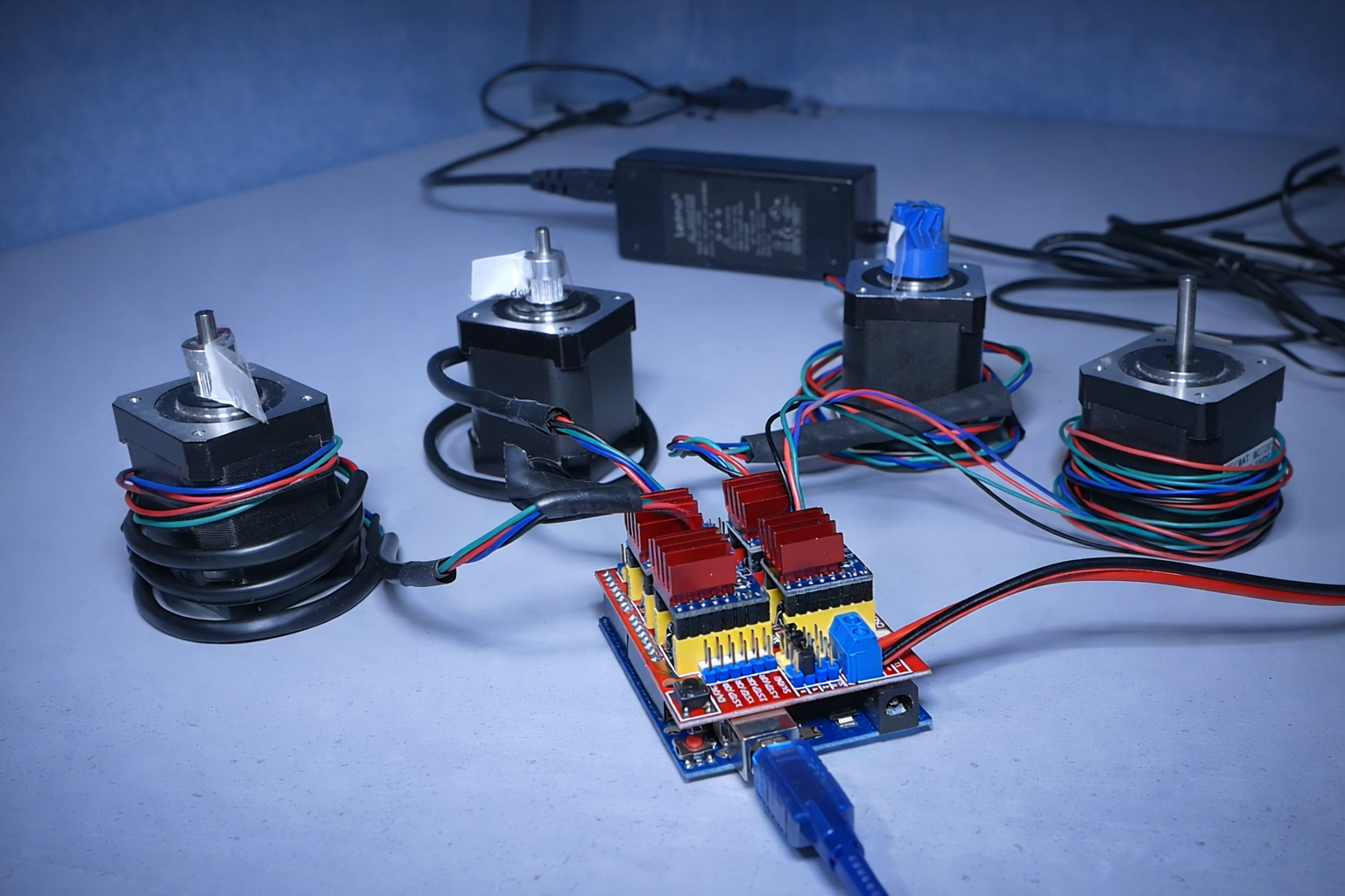
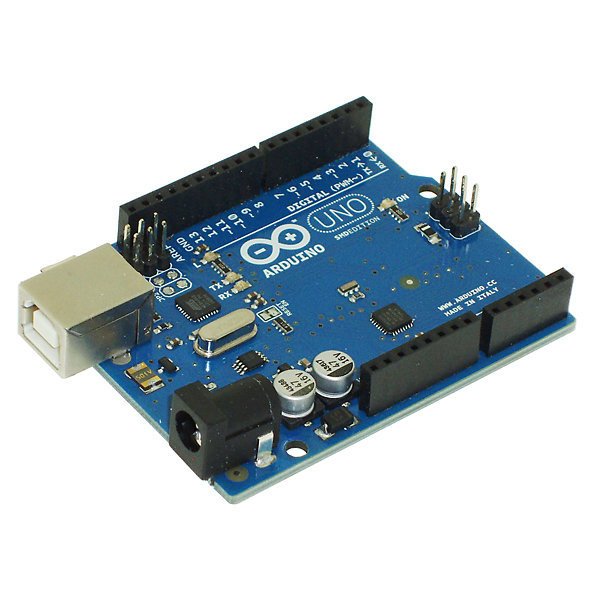
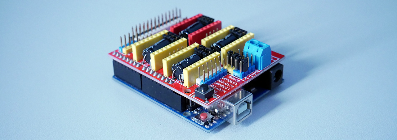
For the electronics I am going to present, we will base ourselves on an Arduino Uno board which is easy to handle, equipped with a CNC Shield V3 from Protoneer:
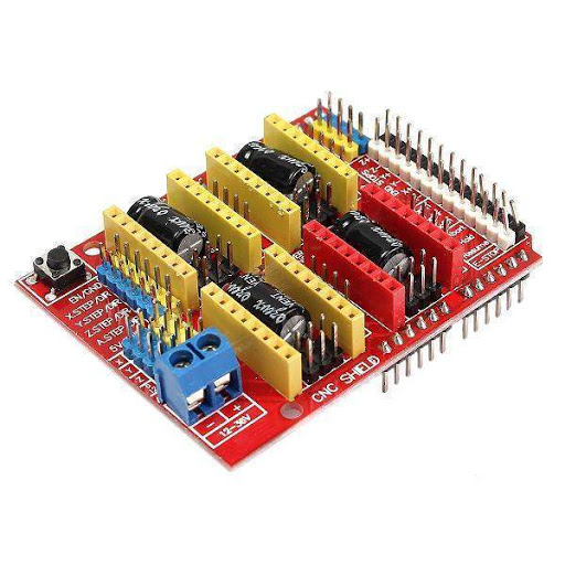
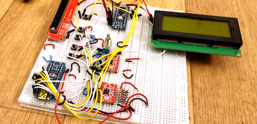
We could have done without the CNC Shield, but already:
- it's long, tedious.
- it's not resistant to dust or vibrations, it's a recipe for short circuits everywhere.
- it's very complicated to integrate neatly into a case because it takes up space and due to point 2, it needs to be well protected.
Here is the kind of setup that the CNC Shield helps to avoid:
For the motorization, we will use Nema17 motors, which are stepper motors, 200 steps per revolution. These are motors used in 99% of consumer 3D printers and CNC machines that can be found almost everywhere on Amazon or elsewhere.
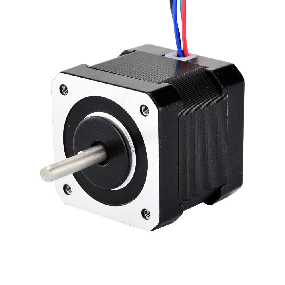
Stepper motors are not conventional motors that you plug into a power supply and they start turning like magic.
They perform a series of "steps" to turn, which allows for precise control of their speed, direction of rotation, and especially their position.
In our case, the Nema17 makes 200 steps to complete one full turn. This means that we can control their position to 360 / 200 = 1.8°!
To make them take a step, you need to send them an electrical pulse. That is to say, to make them turn, you need to send a series of pulses:
- By controlling the number of pulses sent, you control their position.
- By controlling the frequency of the pulses, you control their speed.
You cannot send the control signals from the Arduino directly to the motors, as the motors require much more power than the Arduino can provide.
To convert these control signals into signals capable of powering the motor, we use an electronic component called a motor driver.
In our case, the driver receives control pulses (and the direction of rotation information) from the Arduino, then it amplifies these commands and transforms them into high-power electrical pulses, which it then sends to the motor to make it turn.
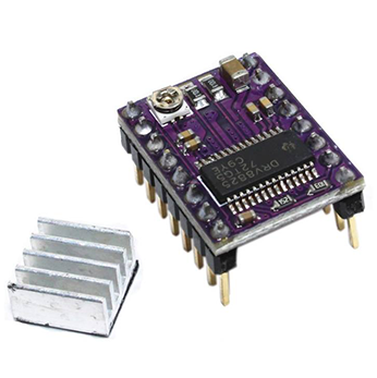
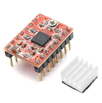
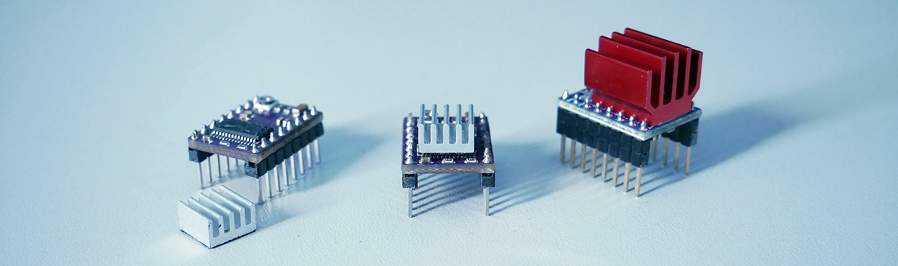
There are 2 well-known HYPER motor driver references: the DRV8825 and the A4988.
(Once again, I know that there are more references for motor drivers, more efficient with advanced features like Trinamic with noise reduction system, step loss detection, etc. but here, I stick to simple things.)
These two motor drivers are protected against overheating (within certain limits, of course) but they have 2 important differences:
- the maximum current that the driver can send to the motor
- the number of "micro-stepping" divisions
Here are the values for these two drivers:
- DRV8825: Accepted current up to 1.5A without cooling, 2.2A with very effective cooling (heat sink + fan). Maximum division of 1/32 for micro-stepping.
- A4988: Accepted current 1.2A with cooling, and 2A with effective cooling (heat sink). Maximum division of 1/16 for micro-stepping.
A higher current will allow for larger, more power-hungry motors and/or allow the motors to be pushed a bit more. Here, the DRV8825 accepts more current, so it provides more margin for choosing your motors.
Micro-stepping, for its part, involves dividing the step of a motor into even smaller steps, thus multiplying the total number of steps of the motor to make 1 full turn.
For example, our Nema17 motor - 200 steps per revolution, with a micro-stepping of 1/2, will perform 200 x 2 = 400 steps to make one turn. So, following the logic, the DRV8825 is capable of multiplying the number of steps of our motor by 32, while the A4988 can multiply it by a maximum of 16.
I naturally prefer the DRV8825 because it accepts more current and has much finer micro-stepping.
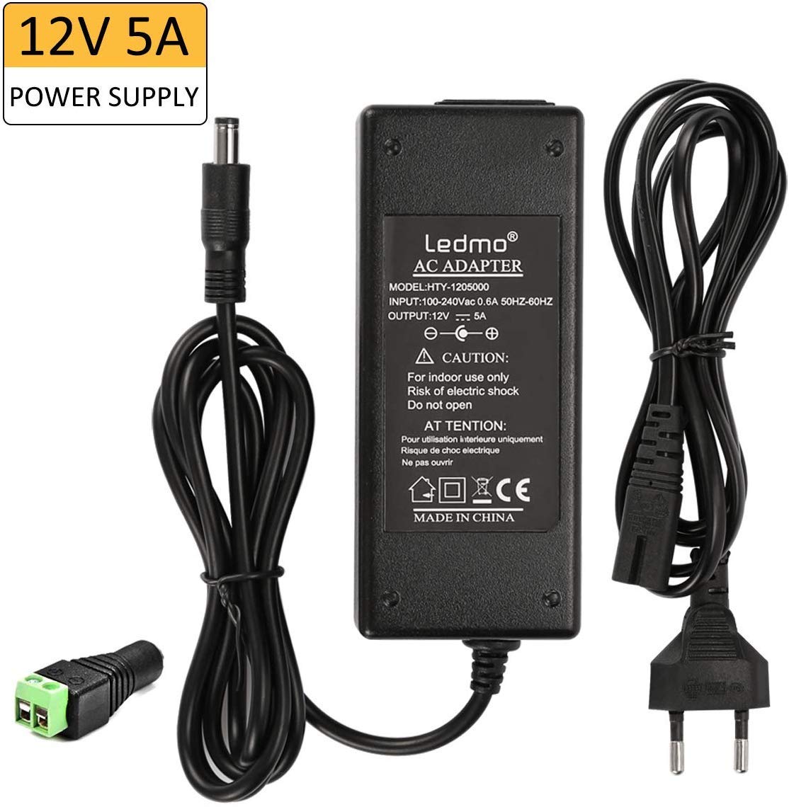
And finally, to power all this, we will need a fairly powerful power supply mainly to support the load of the motors. Each motor consumes about 5W, which gives us 20W for a setup with 4 motors.
I personally use a 12V 5A power supply (about 60W) which is more than sufficient for my use:
Summary of the equipment list:
| Nom | Qté | Notes |
|---|---|---|
| Arduino Uno | 1 | |
| CNC Shield | 1 | |
| Nema 17 motor | 1 - 4 | |
| Motor Drivers (A4988 or DRV8825) | 1 - 4 | |
| Power supply 12 or 24V | 1 |
2 - SOFTWARE
Now that we've covered the hardware a bit, let's look at the software needed to program, configure, and control a CNC.
The first software we will need is the Arduino IDE, which is the Arduino development environment. It is completely free and will allow us to program the embedded software, also known as firmware in English, on our Arduino board. To install it, there's nothing complicated; just download it and follow the classic "Next Next...".
Here is the link to download it: Arduino IDE - Software
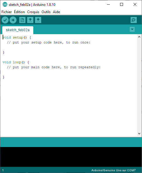
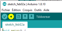
Once you have installed it, launch it to check that it has been installed correctly. You should see this window:
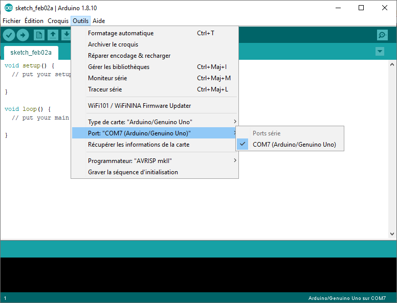
Connect your Arduino board to the computer and check in the "Tools" tab that the software is able to recognize your board correctly.
You can select the communication port (which should appear) and the type of board. Make sure everything is detected correctly; if not, choose the correct type of board.
At this stage, you are able to program your Arduino, but the question is: with which firmware?
We will use the GRBL firmware here, which is open source (free) and widely used in consumer CNCs. It is even used enough that well-known software like Fusion360 integrates the export of machining paths in the GRBL format.
Here is the link to download it: GRBL - Last Release
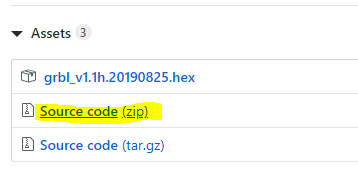
You will need to download the zip "Source code (zip)".
Then you just need to extract it, you should have a tree structure of folders and files. The only folder that will interest us is "grbl".
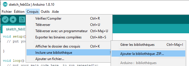
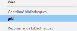
This folder is a library for the Arduino IDE software. So we will go back to the software and include this folder by clicking on "Add ZIP Library" in the "Sketch > Include Library" tab.
There, you navigate to the location where you extracted the folder and select the "grbl" folder (it is not a zip folder, but it works anyway).
After that, when returning to the sketch tab, you should see the grbl library that has appeared in the same tab:
You now have GRBL ready! All that's left is to program the Arduino board with it.
To do this, we will simply open the Arduino IDE project provided with GRBL. Since we added GRBL as a library, we just need to go to "File > Examples > grbl > grblUpload", and the project will open in a new window!
All that's left is to "upload" the program to the Arduino board by clicking on this little button at the top left of the window:
In the black console at the bottom of the window, you should see things passing by, compilation and upload information. You are programming GRBL into your Arduino!
Wait a moment until the programming is complete. The console should look like this, displaying "Upload complete" if everything went well:
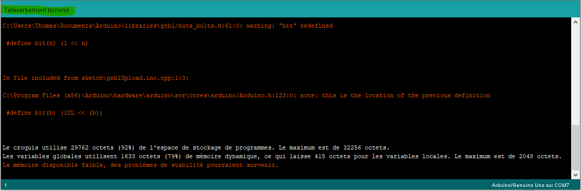
(There are warning messages regarding available memory, this is normal, GRBL uses almost all the available space on the Arduino's memory.)
And there you go! You have programmed your Arduino board with GRBL. The Arduino IDE indicates that the upload was successful, but we still don't have a way to verify that GRBL itself is working properly...
So it's time to introduce the third and final software we will need, I present to you: CNC JS!
CNC JS will allow us to communicate with GRBL. We will be able to configure it but also, and most importantly, control our CNC!
Just like with the other software, we will download and install CNCJS, here is the link: CNCJS - Last release
Once installed, you can launch it, you should see this window:
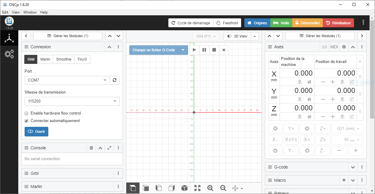
You can see on the left a section titled "Connection". Select the communication port of your Arduino (the same as in Arduino IDE), set the baud rate to 115200 (I won't go into details), then click on "Open".
The "Console" section just below should open and display a bunch of parameters in white on a nice black background:
These parameters are sent by GRBL, which means that GRBL is running correctly. If you scroll up a bit in the console, you should even find the version number of GRBL that you just installed.
We have just completed the installation of the software and the programming of the Arduino. We will also check that GRBL has been installed correctly and that it is responding. We will now move on to assembling the components together.
3 - ASSEMBLY
The assembly is quite simple, it's like Lego!
To start, we will mount the CNC Shield board on the Arduino. At this stage, you really can't go wrong.
Next, we will place the micro-stepping drivers. There are 3 possible slots under each motor driver slot.
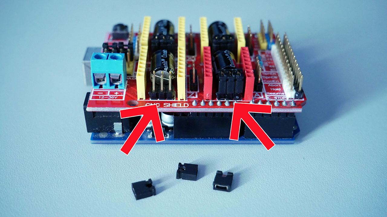
Depending on how the jumpers are positioned, we select the micro-stepping division mode. Here is the correspondence table for each driver reference:
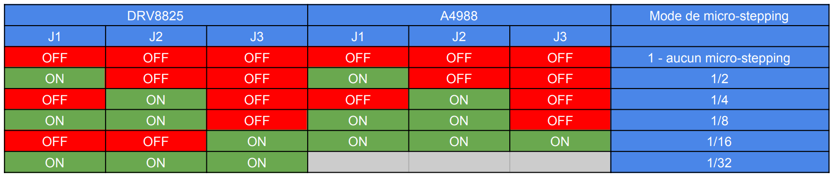
Remember well which mode you selected, it will be very important for what comes next!
Personally, I put all the jumpers on the DRV8825. I am at 1/32 micro-stepping.
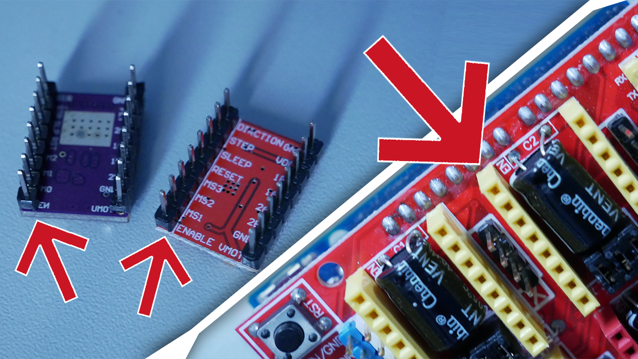
Next, we attach the heatsinks often supplied with the drivers. If, like me, you have a fairly large machine, I recommend buying much larger heatsinks that will better cool your drivers.
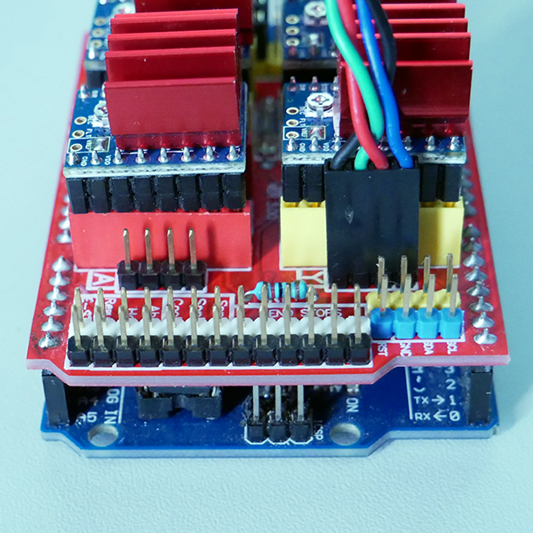
We will be able to place the drivers in their respective locations on the CNC Shield.
WARNING: Here, you need to carefully look and position the "Enable" (or "En") pin of the driver on the Enable pin of the CNC Shield, otherwise you are sure to burn everything out.
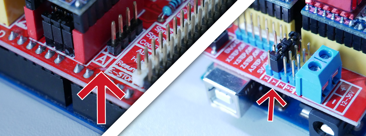
Once you have installed all your drivers while paying attention to the Enable pin, we will focus on the 4th motor driver slot.
On the CNC Shield, next to each motor driver slot, there is the name of the axis that this driver will control (X, Y, or Z), but there is also a 4th driver labeled 'A'.
This 4th driver can replicate all the movements of one of the 3 other axes, of your choice. If, like me, you have a CNC with 2 motors for a single axis, you will need to use this axis duplication feature. (In my case, it is the Y axis that has 2 motors.)
On the side of the CNC Shield, you have slots for jumpers labeled with the names of the axes. You will need to place 2 jumpers side by side to select the axis you want to replicate.
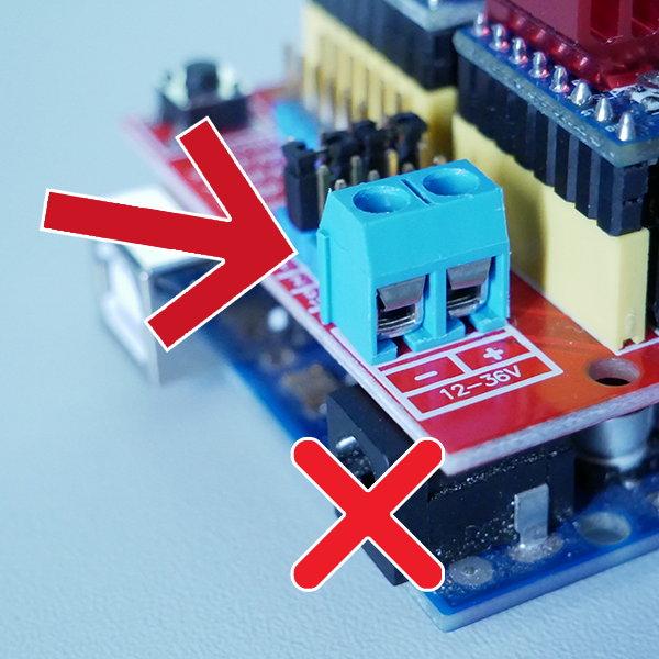
All that's left is to connect the power supply and the 4 motors. For the power supply, it's simple, there is a terminal block on the CNC Shield, we connect the + to the red wire, the - to the black wire...
Be careful though, you should not connect the power supply directly to the Arduino but rather to the terminal block of the CNC Shield. The Arduino will simply be powered by the USB port.
To connect the motors, there is a 4-pin connector next to each driver. There is no specific orientation, as flipping the connector simply reverses the rotation direction of the motor.
Le montage est terminé ! Nous pouvons passer au paramétrage de GRBL.
4 - PARAMÉTRAGE
Pour le paramétrage, on va rebrancher notre Arduino en USB à l'ordinateur et on va alimenter la CNC Shield avec l'alimentation branchée juste avant.
Une fois que tout est branché, nous pouvons retourner sur CNCJS, ouvrir la communication et ouvrir la section console.
Vous devriez avoir comme plus haut tout cela qui s'affiche :
CNCjs 1.9.20 [Grbl]
Connected to COM7 with a baud rate of 115200
Grbl 1.1h ['$' for help]
client> $$
$0=10 (Step pulse time, microseconds)
$1=25 (Step idle delay, milliseconds)
$2=0 (Step pulse invert, mask)
$3=0 (Step direction invert, mask)
$4=0 (Invert step enable pin, boolean)
$5=0 (Invert limit pins, boolean)
$6=0 (Invert probe pin, boolean)
$10=3 (Status report options, mask)
$11=0.010 (Junction deviation, millimeters)
$12=0.002 (Arc tolerance, millimeters)
$13=0 (Report in inches, boolean)
$20=0 (Soft limits enable, boolean)
$21=1 (Hard limits enable, boolean)
$22=0 (Homing cycle enable, boolean)
$23=0 (Homing direction invert, mask)
$24=25.000 (Homing locate feed rate, mm/min)
$25=500.000 (Homing search seek rate, mm/min)
$26=250 (Homing switch debounce delay, milliseconds)
$27=1.000 (Homing switch pull-off distance, millimeters)
$30=17000 (Maximum spindle speed, RPM)
$31=3000 (Minimum spindle speed, RPM)
$32=0 (Laser-mode enable, boolean)
$100=50.000 (X-axis travel resolution, step/mm)
$101=50.000 (Y-axis travel resolution, step/mm)
$102=50.000 (Z-axis travel resolution, step/mm)
$110=500.000 (X-axis maximum rate, mm/min)
$111=500.000 (Y-axis maximum rate, mm/min)
$112=500.000 (Z-axis maximum rate, mm/min)
$120=50.000 (X-axis acceleration, mm/sec^2)
$121=50.000 (Y-axis acceleration, mm/sec^2)
$122=50.000 (Z-axis acceleration, mm/sec^2)
$130=400.000 (X-axis maximum travel, millimeters)
$131=400.000 (Y-axis maximum travel, millimeters)
$132=150.000 (Z-axis maximum travel, millimeters)
ok
>
On va seulement s'attarder sur les 4 paramètres les plus importants.
En premier, le paramètre "$1=25", c'est le paramètre qui va indiquer à GRBL au bout de combien de temps il doit éteindre (dés-alimenter) le moteur après un mouvement. L'unité de ce paramètre est la milliseconde.
Par défaut, après un mouvement, le moteur est éteint au bout de 25 ms.
Un moteur alimenté va forcer pour garder sa position actuelle. S'il est éteint, il n'exercera aucune force pour garder sa position et pourra tourner très facilement.
Prenons l'exemple de l'axe Z qui fait monter / descendre la fraise. Lorsque l'on découpe une planche, le moteur de l'axe Z va faire descendre la fraise dans le bois, puis va rester à sa position durant toute la découpe. C'est là que l'on commence à comprendre le problème.
Si le moteur descend à la bonne position puis s'éteint, vu qu'il n'applique aucune force pour garder sa position, il va très certainement "glisser" plus bas à cause des vibrations pendant le fraisage !
Pour corriger ce problème, il suffit de mettre 255 au paramètre $1. GRBL considère que 255 est un temps infini, donc il n’éteindra jamais les moteurs même après un mouvement. Attention, de 1 à 254, GRBL prendra le paramètre comme des millisecondes, seule la valeur 255 est considérée comme l'infini.
Nous allons donc tout simplement taper cette ligne dans la console :
$1=255
Le second paramètre, c'est le groupe "$100", "$101" et "$102". Il s'agit de la résolution de déplacement pour chaque axe (X, Y et Z dans l'ordre).
La résolution de déplacement s'exprime en pas par millimètre, c'est le nombre de pas que doit effectuer le moteur pour faire déplacer notre machine de 1 mm.
Pour calculer la résolution, il nous faut :
- Le nombre de pas de base de notre moteur (dans notre cas, c'est 200)
- Le mode de micro-stepping choisi, c'est ici qu'il est très important (dans mon cas, 1/32)
- Le système de guidage de la machine (dans mon cas, des vis trapézoïdales 8 mm par tour)
Sur ma machine, j'utilise des DRV8825 et des vis trapézoïdales dont l'écrou avance de 8 mm à chaque fois que la vis fait 1 tour.
Voici donc un exemple de calcul de la résolution basé sur les valeurs de ma machine :
(200 pas (Nema17) x 32 (micro-stepping)) / 8 (vis trapézoidale) = (200 x 32) / 8 = 800 pas / millimètre
Nous allons faire un deuxième exemple pour une machine à courroie GT2. Ce sont les courroies classiques utilisées en impression 3D, elles ont un pas de 2 mm par dent. Nous allons aussi dire que le moteur est équipé d'une poulie de 20 dents et qu'on utilise un A4988 en 1/16 microstepping.
Donc voici le calcul :
(200 pas (Nema17) x 16 (micro-stepping)) / (2 (pas de la courroie) x 20 (nombre de dents de la poulie)) = (200 x 16) / (2 x 20) = 80 pas / millimètre
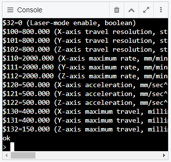
Nous allons donc renseigner cette valeur à GRBL (dans mon cas, 800) :
$100=800
$101=800
$102=800
C'est avec cette valeur que l'on peut calculer la précision atteignable (théorique) par notre machine en divisant 1 millimètre par le nombre de pas :
1 mm / 800 pas = 0,00125 mm
1 mm / 80 pas = 0,0125 mm
Le troisième paramètre, c'est le groupe "$110", "$111" et "$112". C'est la vitesse de déplacement maximale pour chaque axe (X, Y et Z dans l'ordre).
Le quatrième paramètre, c'est le groupe "$120", "$121" et "$122". C'est l'accélération pour chaque axe (X, Y et Z dans l'ordre).
La vitesse s'exprime en mm/min, littéralement "combien de millimètres va parcourir la machine en 1 minute".
L'accélération s'exprime en mm/sec², en gros plus la valeur rentrée ici sera grande, plus l'accélération sera forte.
Ces deux valeurs vont beaucoup dépendre de votre machine, son poids, sa taille et le type d'usinage que vous allez effectuer (une gravure laser peut accepter des accélérations et une vitesse beaucoup plus grandes qu'une découpe de bois, par exemple).
Je ne peux donc pas vous donner les valeurs parfaites pour votre machine... Vous allez devoir faire des essais !
Je peux quand même vous donner un exemple pour avoir des paramètres de départ pour vos essais :
Sur ma machine qui est grande, lourde et qui découpe principalement du bois, j'ai 2000 mm/min en vitesse, et 200 mm/sec² en accélération :
$110=2000
$111=2000
$112=2000
$120=200
$121=200
$122=200
Et voilà, cet article touche à sa fin. Je ferai bientôt un nouvel article sur "comment faire pour générer un fichier d'usinage pour une CNC sous GRBL".
Dites-moi ce que vous avez pensé de cet article en commentaire et quel article vous aimeriez pour une prochaine fois !
A bientôt !