How to control external drivers (e.g. Nema23) with an Arduino
In this article, I will try to explain how to control external drivers with an Arduino.
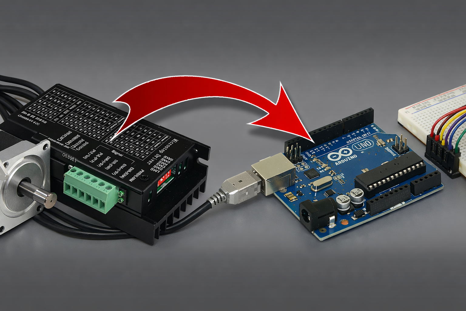
I filmed a video some time ago titled "Connecting NEMA23 to CNC SHIELD". As its title indicates, in this video, I explain how to connect the Nema23 to an Arduino + CNC shield setup, which allowed me to keep a Nema 17 motor for the Z axis by using a small onboard driver to connect directly to the CNC shield.
If this is what you are looking for, I will share it again here
1 - MATERIAL
For this article, I will use an Arduino Uno board with GRBL 1.1 installed on it.
Here is the link to the GitHub of GRBL 1.1 for Arduino Uno / Nano: https://github.com/gnea/grbl
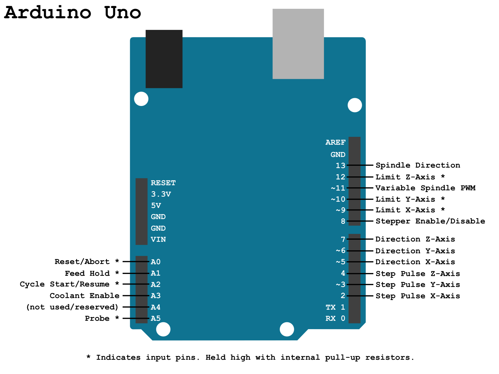
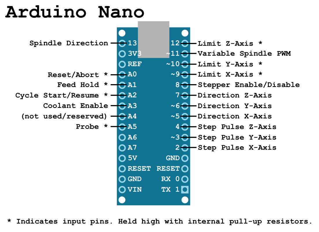
Here is a reminder of the "pinout" of GRBL 1.1 for the Arduino UNO / Nano.
Here is the link to the GitHub of GRBL 1.1 for Arduino Mega: https://github.com/gnea/grbl-Mega/
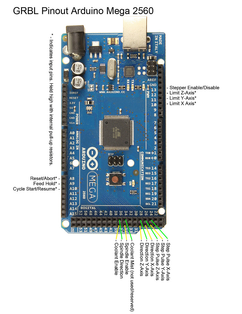
Here is a reminder of the pinout of GRBL 1.1 for the Arduino Mega.
2 - A LITTLE THEORY
Before I start explaining how to connect your drivers to your Arduino, let's go over a bit of theory (very quickly).
(If you're not interested in understanding how it works, you can skip directly to the "wiring" section.)
Most motor drivers available commercially need 3 things to operate:
2.1) A power supply
For this, I can't help you, it depends on your drivers, you'll need to check their documentation. For my part, they are "DM542Y" and they are powered at 36V between the terminals labeled V+ and V-.
2.2) A "direction" signal
This is the signal called "Direction" on the pinouts above. It has 2 states, ON or OFF (5V or 0V) which correspond to a direction of rotation.
This is the signal that will indicate to the driver in which direction to turn its motor, quite simply.
2.3) A "step" signal
You guessed it, this is the signal called "Step" on the pinouts above.
This is the signal that will tell the driver to move the motor forward by 1 step, taking into account the "micro-stepping" configured on the driver (via a series of small jumpers or small ON/OFF switches like on my driver).
If you have configured 2000 steps per revolution on the driver (or micro-stepping of 1/10 on a 200 steps/revolution motor), each pulse of this signal will make the motor take 1/10 of a step. Therefore, the Arduino will need to send 2000 pulses on one of its outputs to make the motor turn 1 complete revolution.
And yes, it is the Arduino that calculates/generates all the motor steps, not the driver. The driver simply translates each 5V pulse that the Arduino generates to a higher power level (24V in my case).
Small aside: You understand here the interest of not unnecessarily increasing the number of micro-steps if the precision is already sufficient at a lower micro-stepping level.
If you set a micro-stepping that is too high, your Arduino will have to send tens of thousands of pulses to make a motor turn 1 revolution, imagine when it has to move 3 motors at the same time! We quickly exceed hundreds of thousands of pulses to calculate and then generate…
For example, a machine has:
- 3 motors 200 steps/revolution
- The motor drivers set to 256 micro-steps
- A standard T8 trapezoidal screw, with a feed of 8mm per revolution.
For each revolution of a motor, the Arduino will need to generate 200x256=51,200 pulses. This value is multiplied by 3 because we have 3 motors, so 3x51,200=153,600 pulses to move each axis by 8mm at the same time.
Now, let's imagine you want to move 20mm and raise the Z-axis by 20mm at the same time at a speed of 1150mm/min on each axis. Such a movement takes about 1 second ((20/1150)*60) and requires the Arduino to generate 153,600*2.4=368,640.
368,640 steps per second, or 368kHz, is huge. It seems to me that GRBL on an Arduino Uno can hardly exceed 100kHz.
In terms of precision, that gives you 8/51,200=0.00015625mm! For comparison, the thickness of a hair is about 0.05mm... for my part, I now set all my micro-stepping to achieve a precision of 0.01mm, which is more than sufficient (even too much) for hobbyist machines.
Between vibrations, lack of rigidity, the runout of our routers, and the often questionable quality of our AliExpress end mills, that is already a precision that is practically impossible to achieve.
Conclusion of the aside: Set your micro-stepping to achieve just sufficient precision, don't exaggerate, it will only bring you problems and unnecessarily limit your machine.
2 - WIRING
You will have understood, I think, to wire the external motor drivers, you simply need to connect the Step and Direction signals from the Arduino to the Step and Direction inputs of the drivers.
On some drivers like mine, the term "STEP" may be replaced by "PULSE" or "PU" and the term "DIRECTION" may become "DIR" or "DR".
If you pay closer attention to the Arduino pinout, it mentions a single pin for step and a single pin for direction on each axis, and if you look at your driver, it expects a "step +" and a "step -" as well as a "direction +" and a "direction -".
It's very simple, the "minus" corresponds to the ground of the signal, so you can connect all the "minus" of each signal and each axis together to the GND of the Arduino.
And then… that's it!
You just need to connect your motors to your drivers by connecting the A+ A- B+ B- wires of your motors to the corresponding terminals on the driver. Again, I can't really help you here, you'll need to check the documentation for your motors.
For my part, they are Nema23 StepperOnline, here is their wiring if you have the same:
| A+ | A- | B+ | B- |
|---|---|---|---|
| Noir | Vert | Rouge | Bleu |
There you go, let me know if this article helped you, otherwise we'll meet on the forum to answer your questions! See you!