
Nothing much new to report - have three new designs to share (none of which are useful) - and an offer to any fellow Australian's that might be reading.
First up - I've got spares printed of things - and will be following the upgrade path of replacing my plastic bits with metal bits once I've got mine up and running properly - so if you are in Aus and thinking of doing this later this year.. hit me up and I might be able to save you a lot of printing.
Gantry top cover plate: https://www.thingiverse.com/thing:5408901
Topsie has used a couple of aluminum plates for this part, which is probably a much better idea for strength. I'm printing all my parts in Xpla which is very strong, with really thick walls and 50% infill.... but I won't be surprised if this doesn't hold up to working stress and I replace it with metal... I just like how it looks and hopefully it will last at least long enough to help cut the replacement part.
Gantry side plates: https://www.thingiverse.com/thing:5408904
Same again really :)
And finally - dust collection. My current "heavy" makes a lot of dust. Tremendous amounts of dust. I cut firebrick with my router, and even with my dust extractor running my machine area gets absolutely covered in dust when I'm doing a batch of bricks (which is why I do about 500 at a time over the course of 2-3 days then spend half a day cleaning up) So I'm going to be building a lot of extra dust mitigation into my new one (including a full length collection area at the back of my spoilboard where a vast amount of dust gets flung during the cutting process) and a good spindle collection system is an important part of my plans. Whatever I end up using will be posted here.
I also want to connect my dust collector to the vertical extrusion rather than the spindle so that it stays at a constant height during machining to let me keep it riding just on top of my pieces (I do multiple machining heights during a cut, and they vary by too much to take up the difference with bristles) - so here is my first, designed while slightly drunk, version. It is very wrong - and I forgot to take into account the height of the gantry off the table, but I've got a vertically scaled down version printing to check clearances. I'm very open to thoughts, comments or alternative suggestions.
https://www.thingiverse.com/thing:5408407
It has an 80mm hole for the spindle (which I'll have to open up slightly to allow the spindle to glide through...) and a 100mm hole for my collection hose (which I'll have to open up to 101.. but in my defense I had been drinking). The tabs on the back side should allow it to bolt to the extrusion and clear the spindle mounting plate.
Well - that first idea was terrible, so I think I'll aim to split it into two parts like the "more depth" extractor from the last one. I've got a vertically scaled version of this printing:
https://www.thingiverse.com/thing:5410614
It suits a 90mm pipe (because I actually measured my pipes this time). My plan is for this pipe to hold up the dust boot, then this pipe will connect by a flexible pipe to the main extraction system
Will see how it goes, but it should fit and enable me to clamp the dust pipe to the vertical extrusion (might use two of them) and then I'll see how its all looking. I'm still busily trying to get through my stockpile of bricks so I can scavenge the motors etc from my current one before doing any more actual building.
Ok, have a bottom piece now - have printed two of the bits in the post above to give a really solid hold on the tube - and currently printing this:
https://www.thingiverse.com/thing:5411510
It is designed for a 5mm wide brush strip... I don't know if it works yet, so please don't print one unless you feel like maybe wasting plastic.
Hopefully then it will cut down on the dust - Ive got the front and back vents to print too and then get it all wired and connected.. should be a big weekend.
I broke my regular "heavy" cnc yesterday, and could fix it easily enough (it is just a printed coupler that has failed after several hundred hours of running) - but I've decided instead to press ahead and get this one running quicker.
Hi folks - not much of an update today - but 2 new parts:
https://www.thingiverse.com/thing:5413769
and
https://www.thingiverse.com/thing:5413768
Bits for either end of the Z axis extrusion if you are using profile 30 extrusion which needs m8 bolts rather than m6 bolts. Again, you could just print the ones in the download and drill them out to an 8mm hole and a 13mm recess - but I like to print.
Dust collector printed well, is a little small for my 90mm pipe, but I just sanded it a little bit and it is tight as a glove. Tomorrow should be final assembly and then just wiring etc to go. My new dust boot brush won't be here for a few days, but I'll test dust extraction without it and see if its just a bad idea.
Short update - mechanically assembled, one problem found with my gantry spacer block. It is 1mm too long. The file is here: https://www.thingiverse.com/thing:5405853 and it should be 74mm tall. If you already downloaded one that is 76mm in one axis - I would just manually resize it. I've just uploaded a new V2 version for people in the future.
If you happen to have already printed one you can fix it the same way I did - sand a little bit where the linear rail hits it. If you are printing with the settings that Topsie recommends there is plenty of solid wall to file off before you get into infill.
Mine is too tall - the legs are 1m long and with the wheels etc it is too big for me to load comfortably, I'll probably cut the legs down to 85-90cm to make it easier (I'm 190cm tall).
Tomorrow I'll be wiring and installing limit switches (I know they aren't needed, I just like a backup system in place in case I make a mistake), and hopefully before the weekend will be up and running again (I have some work that needs to be done, it can't all be playing with CNC's)
Hello,
I draw the heavy Metal on Fusion 360.
I modified some parts (i used a HM1257 instead of XY_Nema23_holder_part1 by example).
But i have a question on the Z axis.
Why it's so length ?
I used an aluminium profile of 500mm and a linear rail of 450mm.
On my Y cart, i used an aluminium profile of 340mm.
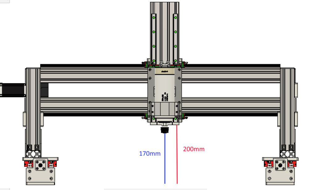
First img : ZAxis-
Between the XGantry and the spoilboard (36mm), i have 200mm approx (red line).
For the ZAxis- i have 170mm approx (blue line) between the spindle and the spoilboard
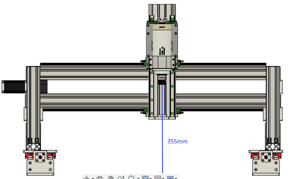
Second img : ZAxis+
For the ZAxis+ i have 355mm approx (blue line) between the spindle and the spoilboard.
So even with a long mill, i don't understand why we have a so long ZAxis.
I could decrease the ZAxis of 50mm but in this case we loose some space between the bottom of the ZAxis and the spoilboard (third img)
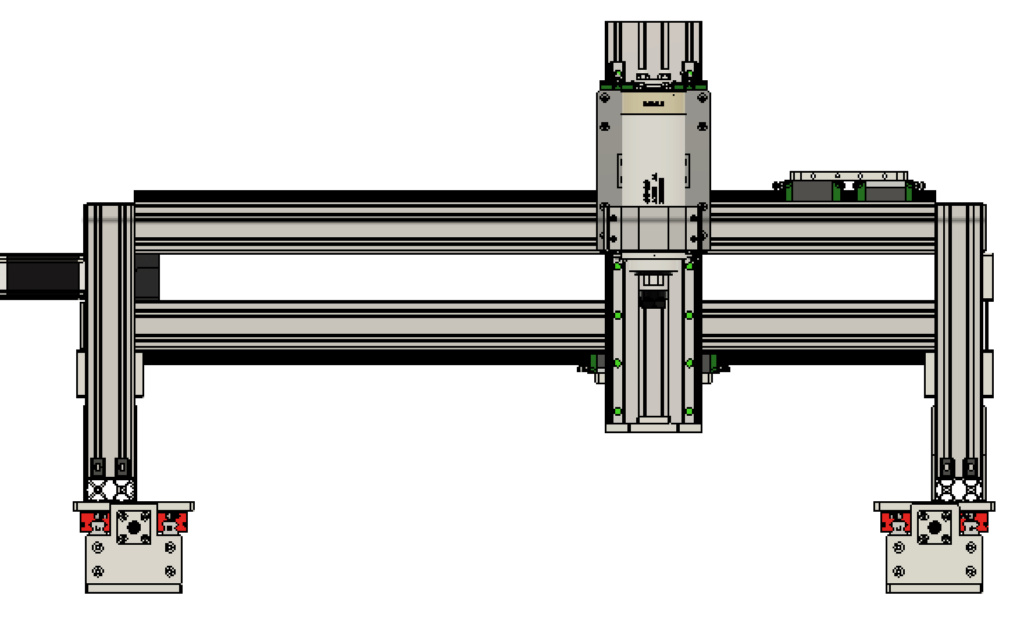
Maybe i don't understand something but i think i will decrease the length of my ZAxis Linear Rail and the height of the X Gantry.
Do you have some advices ?
Good morning,
I think the big difference between how Topsie has built his and your fusion design is the mounting position of the spindle - yours is clamped near the working end and his is clamped near the top.
The absolute best part about a DIY CNC is that you can modify it to suit your needs rather than having to live with something that suits most people. If all you are doing is working with aluminum pieces than you probably want maximum rigidity and have minimal clearance requirements - in which case you could probably shorten your gantry height by...100mm? and you can probably shorten your Z axis too (I'm not sure by how much, I'm not in front of mine till later today - I'll give it a measure later and update).
Your X axis gantry thickness is 180mm, plus bearings plus "X cart to Z axis connectors" for a total of 330mm and you lose 20mm of linear rail length in the mounting block too - so the absolute minimum length for your Z axis will be 350mm, but this won't allow any travel at all... I think - again I'll measure it later to know for sure.
Someone like me who works mostly with large but soft things doesn't need rigidity as much, but needs maximum clearance - I might make my gantry taller later - Or drop my spoilboard down more - to get a full 200mm clearance.
I think there won't be any rigidity benefits to having a shorter Z axis - just maybe additional costs, but very minor ones. From my supplier a 500mm ballscrew was $62, and a 350mm one would be $56 and it is very similar with the linear rails (remembering that the rails need to be 50mm shorter than the ballscrew).
There could be benefits with shorter gantry legs - but you can always make them smaller later, its hard to make things longer :) One of my jobs for the weekend is to shorten my 60x60 legs because I can't comfortably get to the center of my table without a ladder - and I think I'm going to cut them down by 240mm to be able to use the offcuts to make my gantry mounting plates 60x60's rather than 60x30's to get me 30mm more clearance.
Cheers - and good luck!
Sorry for the delay - life gets in the way.
Measuring my Z axis the smallest you could make it would be 100mm shorter - with a 400mm extrusion, 400mm ballscrew and 350mm linear rails.
With the standard setup there is 220mm of travel for the spindle - so if you do shorten it that will decrease by whatever amount you cut off. Personally I would leave it alone.
My maximum clearance is 205mm - but that doesn't include the thickness of the spoilboard.
New part day: Drilling template for all flat alloy bits. It is full of 4mm holes for using an automatic centre punch. It should work for all pieces, just fit whichever piece into the corner.. it will be obvious when you print one. Here you go: https://www.thingiverse.com/thing:5418910
Tks Nothos
I've started to seriously look at the Tops Heavy Metal CNC since I think its DIY cost-to-build ratio for the provided performance is the best I've seen, and I've spent some time looking.
First, thanks to Topsie for making it all happen and nothos for creating parts to complete the Heavy Metal CNC's BOM!
The one thing that I noticed is nothos posted the stepper motor ends need 6201zz bearings - 2 per stepper motor. The other ends need 6000zz bearings - two per end.
The 6000zz bearing is easy to find, but all the 6202zz bearings I found had dimensions of ID = 12mm x OD = 32mm x W = 10mm which is in conflict with the SFU1605 ball screw which has end diameters of 10mm.
I found a 6201/10 2RS that seems to fit at ali express:
https://www.aliexpress.us/item/2251832811068642.html?gatewayAdapt=glo2usa&_randl_shipto=US
Other than that I think it's a go!
Also, it would be great if I could get feedback on improvements and enhancements for those who have built the Heavy Metal V1.
Thanks,
DDG